10 30 minutes
Robot control knob
A human hand steering a motor through a number
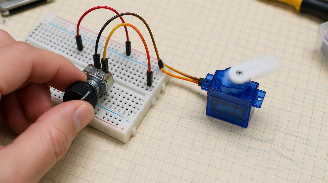
Mission goal: Combine the Mission 09 servo circuit with the Mission 07 potentiometer so turning the knob commands the servo's pulse width in real time.
Section 1
Understand
New ideas
- Mapping one range onto another
- Integer division for clean whole numbers
- Low-voltage sensing and high-current motion in one project
- Why a clamp still matters after a map
- 1The knob reading becomes a servo pulse between 1200 and 1800 µs.
- 2Pot on 3.3 V, servo on its own 5 V, grounds shared.
- 3The drawn angle is illustrative, not measured.
Safety first
- The servo must be powered from an external REGULATED 5 V supply able to deliver at least 1 A, with a suitable insulated connector. That supply may be an extra purchase beyond the kit, and an adult must check it before it is used.
- Never power a servo from a GPIO pin or from the 3V3 OUT pin. A servo pulls far more current than those pins can give, and trying it can damage the board.
- The external supply's positive wire connects to NO Pico pin at all. Not VBUS, not VSYS, not 3V3. The Pico stays powered from the USB cable.
- The only thing shared between the two power systems is ground: the external supply's 0 V connects to Pico GND at physical pin 38. Without that shared ground the servo cannot understand the signal.
- Secure the servo to something solid, such as taping it to a heavy book, before powering it. A loose servo whips around.
- Test with the horn removed, or at least with nothing attached to it. The very first command can make the servo jump suddenly to a new position.
- Actual lead markings on your servo override any colour convention. Red is usually positive and brown or black is usually ground, but check the printed markings or the supplier's documentation.
- If the servo buzzes continuously, gets hot, or is clearly straining against something, cut the motor power immediately.
- Switch BOTH the USB power and the external supply off before any rewiring, and before fitting or removing the horn.
- The knob is powered from Pico 3V3 OUT at physical pin 36. Keep the 5 V supply well away from the potentiometer.
- Give each potentiometer leg its own breadboard row so you cannot short 3.3 V to ground.