14micro:bit · MakeCode 35 minutes
Servo bench test
Command a positional servo on P1 with a separate 5 V supply.
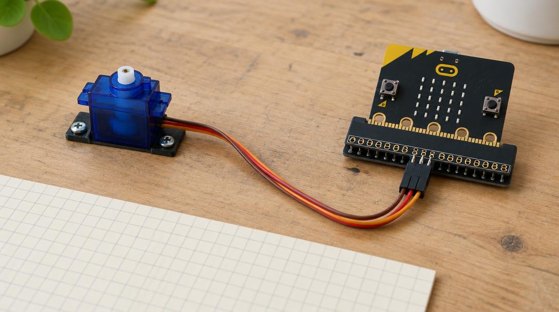
Lesson goal: Run a finite servo test on A (1500, 1400, 1500, 1600, 1500 µs) and stop pulses on B, with external regulated power.
Open MakeCodeSection 1
Understand
- servo pulse width
- external supply
- shared ground
- clamping
- 1Servo signal on P1; power from a separate regulated 5 V supply.
- 2Grounds shared. External + touches no micro:bit pin.
- 3Test unloaded: 1500, then 1400 and 1600 µs. B turns pulses off.
Safety first
- Adult setup required. The servo needs an external REGULATED 5 V supply rated at least 1 A, with a suitable insulated connector. This may be an extra item not in the box.
- External 5 V positive goes ONLY to the servo's positive lead. It connects to no micro:bit pin, not the 3V ring, and not the battery connector.
- External supply negative connects to the servo ground AND to the micro:bit GND, so both share a reference.
- The micro:bit stays powered by USB. Never power a servo from a pin or the 3V ring.
- Lead colours are usually red = positive, brown/black = ground, orange/yellow = signal, but markings on your servo override colours.
- Clamp the servo down. Test first with the horn removed. The first command can make it jump.
- If it binds, buzzes, heats or stalls: disconnect motor power at once. Turn off both supplies before any rewiring or fitting the horn.
- micro:bit pins are 3 V logic. Never connect 5 V, a battery pack or anything from a 5 V supply to any ring, port or the 3V ring.