06micro:bit · MakeCode 30 minutes
First external LED
Use the breakout adapter and switch an LED on P0.
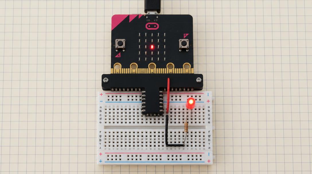
Lesson goal: Wire P0 → 1 kΩ → LED → GND and blink it with digital write.
Open MakeCodeSection 1
Understand
- T-breakout adapter
- breadboard rows
- digital output
- current-limiting resistor
- LED polarity
- 1P0 → 1 kΩ → LED long leg; short leg → GND.
- 2digital write 1 turns it on, 0 turns it off.
- 3Do not play music while P0 drives the LED.
Safety first
- Unplug the USB cable before you add, move or remove any wire. Plug back in only after an adult or you have re-checked every connection against the table.
- micro:bit pins are 3 V logic. Never connect 5 V, a battery pack or anything from a 5 V supply to any ring, port or the 3V ring.
- Always use the 1 kΩ resistor with every LED.